


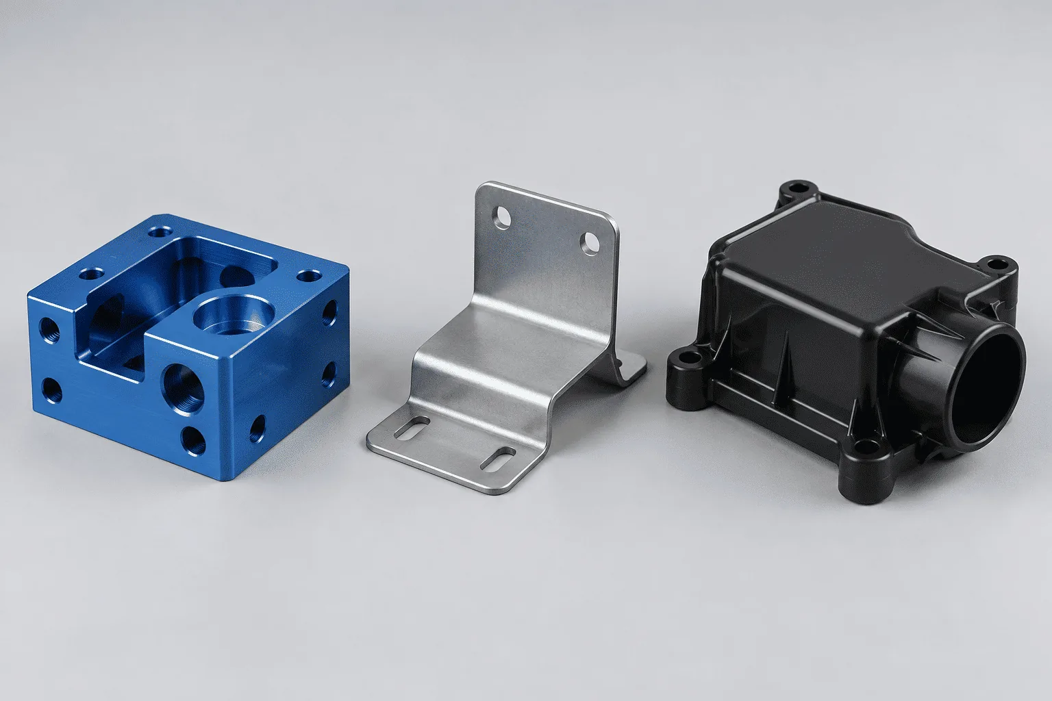
Three routes, same brief: a machined block, a formed bracket and a molded housing. The choice is decided by volume and geometry, not preference.
Every week an engineering team finishes a CAD model and asks the same question: "What should we make this out of, and how?" The answers they get are usually shaped by whoever is asked. A machine shop proposes CNC. A printer proposes 3D printing. A molder proposes tooling. All three are correct at some volume, and all three are wrong at some other volume.
The useful question is not which process is best. It is which process gets this geometry, in this quantity, to a validated part at the lowest total cost — counting tooling, scrap, lead time and the cost of being wrong.
Not the volume in the business plan. The number you need to validate the design, plus the number you need to ship in the first six months. Those two numbers are usually an order of magnitude apart, and they may not belong to the same process.
Prismatic parts with constant wall thickness — brackets, enclosures, chassis, panels — belong to sheet metal fabrication. Parts with complex 3D contours, internal channels or thick sections belong to machining or additive. Parts with draft-friendly geometry and a need for identical reproduction in the thousands belong to injection molding.
A cosmetic cover and a load-bearing bracket made from the same CAD model are different problems. Load paths, fatigue, temperature and chemical exposure narrow the material list, and the material list often eliminates processes before cost is even discussed.
"Rapid prototyping" is a scheduling promise, not a technology. Four distinct routes sit under it, and the right one depends on what you are trying to learn from the prototype.
Subtractive machining produces the real material — the same 6061-T6 or 7075-T651 or POM you intend to use in production — with tolerances that let you assemble and functionally test. Wall thickness down to about 0.8 mm in aluminum is practical; features can be threaded, bored and reamed exactly as in the final part.
Best for: functional testing, fit checks against mating hardware, and any prototype that must survive real loads. Lead time is typically 3–7 working days from approved drawing, and the cost per part drops quickly with quantity because the setup is amortised.
Stereolithography gives the smoothest surface and the finest detail, which makes it the right choice for visual models, snap-fit evaluation and investment-casting patterns. Selective laser sintering in nylon produces tougher, more isotropic parts suitable for light functional testing and small-batch end use.
The limitation is material honesty: an SLA part is not the production polymer, so it can confirm geometry but not mechanical behaviour under load, heat or chemical exposure.
A printed master is used to make a silicone mold, from which 10–50 polyurethane parts can be cast. This is the cheapest route to a small batch of parts in a production-like material with a rubber or rigid feel, and it is the standard approach for pilot builds before steel tooling is committed.
Best for: 10–50 units for field trials, user testing or trade shows, where tooling cost cannot yet be justified.
If the production part will be formed from sheet, prototype it from sheet. Laser cutting and press-brake forming produce a part with the correct grain direction, bend allowance and springback behaviour. A machined-from-solid "prototype" of a sheet metal bracket will fit differently from the production part, because the forming process changes both the geometry and the residual stress.
| Route | Typical lead time | Material honesty | Best used for |
|---|---|---|---|
| CNC machining | 3–7 days | Production material | Functional and fit testing |
| SLA / SLS | 2–4 days | Surrogate polymer | Form, fit, visual models |
| Urethane casting | 7–12 days | Near-production elastomer or rigid | 10–50 unit pilot builds |
| Sheet metal prototype | 3–6 days | Production material and process | Brackets, panels, enclosures |
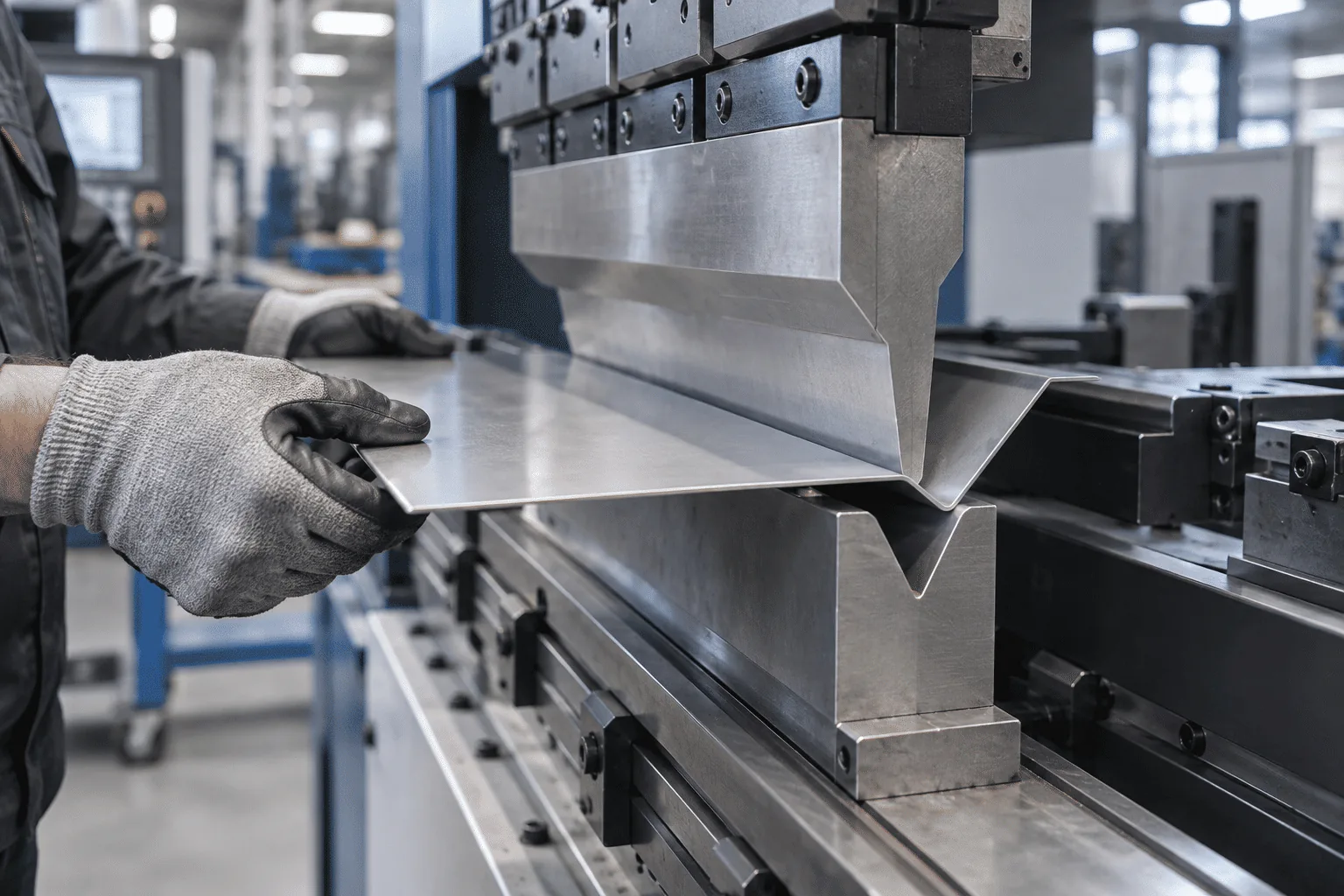
Bend radius, bend relief and hole-to-bend distance are decided in CAD and paid for at the press brake.
Sheet metal fabrication is deceptively simple in CAD and unforgiving in production. The cost is driven less by the outline than by a handful of rules that determine whether a part is one laser program and three bends, or a welded assembly with a fixture.
Every bend needs an inner radius at least equal to the material thickness for mild steel and aluminum, and larger for high-strength or hard tempers. Specify the radius; if you leave it to the shop, the flat pattern they calculate may not match your model, and the assembled part will not close.
The neutral axis does not sit at the mid-thickness. Depending on material and radius-to-thickness ratio, it sits at roughly 0.33–0.5 of the thickness from the inside face. This is why a flat pattern exported directly from CAD without a bend table produces parts that are consistently a few tenths of a millimetre short.
A hole placed closer than about 2.5 times the material thickness plus the bend radius to the bend line will distort during forming. The usual remedies are to move the hole, add a relief cut, or accept a post-form drill operation that adds cost. Deciding this at design time is free; discovering it at the press brake is not.
Where two bends meet, the material must have somewhere to go. Without a relief notch, the corner tears or buckles. A relief of at least the material thickness, cut slightly past the bend line, prevents both.
A welded assembly needs a fixture, a weld sequence to control distortion, and post-weld straightening or machining. If a design can be made as one folded part with a tab-and-slot joint instead of four welded plates, the cost typically drops by 30–50% and the dimensional consistency improves, because there is no heat input to warp the part.
Powder coating adds 60–100 µm per surface and will bridge small holes and tight tolerances. If a hole is a locating feature, specify it as masked, or expect to ream it after coating. Masking labour is often the largest single line item on a small powder-coated bracket.
Injection molding has the highest fixed cost and the lowest marginal cost of the three processes. The entire decision is a break-even calculation plus a geometry check.
Take a palm-sized ABS enclosure. Machined from solid, the part might cost $45 at 50 units. A single-cavity tool for the same part might cost $6,000–$9,000, with molded parts at $3.50.
At 100 units: machining ≈ $4,500; molding ≈ $9,350. Machining wins.
At 500 units: machining ≈ $22,500; molding ≈ $10,750. Molding wins decisively.
Break-even sits near 150–200 units for this part, and shifts with part size and tool complexity.
The break-even point is not fixed — it moves with tool cost, which moves with part size, number of cavities, surface finish requirements and whether the tool needs slides or lifters.
Wall thickness: keep it uniform, typically 1.5–3 mm for ABS and polycarbonate. Thick sections sink; thin sections short-shot. Transitions should be gradual, not stepped.
Draft: 1–2° on all vertical faces, more on textured surfaces. Zero draft means the part will not eject cleanly, and the fix is a tool modification, not a process tweak.
Ribs: rib thickness at 50–60% of the nominal wall. A full-thickness rib creates a sink mark on the opposite face.
Gate location: determines weld line position and flow orientation. Decide it with the molder before the tool is cut, because a weld line across a cosmetic face is a permanent defect.
Undercuts: each one adds a slide or lifter, often $800–$2,500 in tool cost, plus maintenance risk.
A new tool typically requires two trial rounds. T1 confirms the tool produces a part; T2 confirms the part meets specification after adjustments. Teams that compress this to a single trial usually pay for it in the first production run, when the dimensional report shows a trend that a second trial would have caught.
When volume is real but timing is not, a bridge tool — aluminum instead of hardened steel, single cavity, lower cycle life — costs 40–60% of a production tool and delivers parts in 3–5 weeks instead of 6–10. It buys the schedule to validate the market before committing to a multi-cavity steel tool.
| Quantity | CNC machining | Sheet metal | Injection molding |
|---|---|---|---|
| 1 | Best — no tooling | Good for flat/formed parts | Not viable (tool cost) |
| 50 | Strong; setup amortised | Strong for enclosures | Marginal; consider bridge tool |
| 500 | Costly for complex geometry | Competitive if design suits folding | Usually the winner |
| 5,000 | Rarely competitive | Competitive for simple parts | Clearly the winner |
Two caveats on this table. First, it compares processes for the same geometry, which is often the wrong comparison — a sheet metal bracket redesigned for molding is a different part with different tooling economics. Second, it ignores the cost of a redesign. Switching process mid-program usually costs more than the unit-price difference the switch was meant to capture.
CNC plus sheet metal: a formed enclosure with machined interface plates. Cheap where forming is cheap, precise where precision is required.
Bridge tool plus CNC inserts: molded housing with machined metal inserts for threads and wear surfaces, avoiding tool-side thread features.
Prototype in production material: when the prototype must survive the same test as the product, machine it from the production polymer rather than printing a surrogate.
Prototyping in the wrong material and treating the result as validation. A printed part that passes a drop test says nothing about the molded part's notch sensitivity.
Committing to tooling before the design is frozen. Every engineering change after T1 costs tool modification time, which is measured in weeks.
Designing sheet metal parts with machined-part habits. Sharp internal corners, holes on bend lines, and zero bend radius are all normal in CAD and all expensive in production.
Ignoring finishing in the cost model. Powder coating, anodizing and masking can add 20–40% to a sheet metal part's cost, and they are routinely omitted from early estimates.
Choosing the process before the quantity is known. This is the root cause of most of the four above.
Rarely at high quality. Machining, sheet metal and molding require different equipment, different process engineering and different quality systems. The practical arrangement is a supplier with in-house machining and sheet metal, plus a vetted molding partner — with one point of accountability for the program rather than three independent quotes.
For a machined or formed part: 2–4 weeks from frozen design to validated prototype, then 2–4 weeks for the first production batch. For a molded part: add tool design and T1/T2, typically 6–10 weeks total with a steel tool, or 3–5 weeks with a bridge tool.
Below roughly 150–300 units for a small part, machining or urethane casting is usually cheaper once tooling is counted. Above that, molding wins quickly as tool cost amortises. The exact crossover depends on part size and cavity count, and it is worth calculating rather than assuming.
For machining and molding, a 3D model is effectively mandatory — the CAM program and the tool path are generated from it. For sheet metal, the 3D model plus a flat pattern with a bend table is ideal, though a dimensioned 2D drawing with bend lines is workable for simple parts.
Machining holds the tightest general tolerances, typically ±0.01 mm for commercial work and ±0.005 mm on critical features. Sheet metal holds roughly ±0.1–0.2 mm on formed dimensions, driven by springback and tooling. Molding holds ±0.05–0.1 mm on stable dimensions, but shrinks and warps in ways that depend on wall thickness and gate position, so tolerances across a parting line need to be agreed explicitly.
If you need fewer than roughly 50 parts and the geometry is 3D, machine it. If the part is a panel, bracket or enclosure, form it from sheet from the first prototype onward. If you need hundreds to thousands of identical parts with draft-friendly geometry, mold it — and consider a bridge tool to get there without waiting for steel. Prototype in the material and process you intend to produce in, freeze the design before tooling, and treat the first article as a gate rather than a formality.
We run machining and sheet metal fabrication under one roof, and quote rapid prototyping and injection molding as part of the same program, so the process decision is made against your volume rather than against our equipment list. Send a model and a target quantity and we will tell you which route is cheaper — including when it is not ours.
