


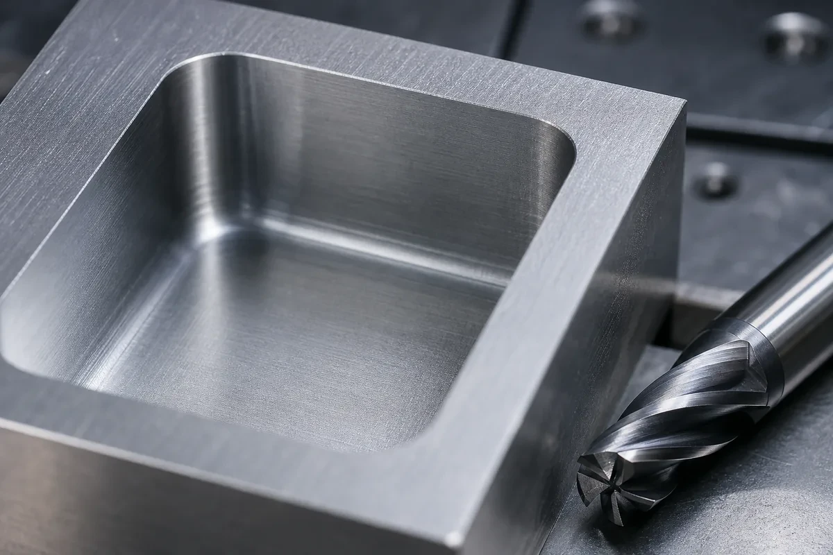
Design for manufacturing is usually presented as a list of prohibitions. In practice, most of the rules exist because a specific geometry forces a specific, more expensive operation — and once you know which operation, the rule stops being arbitrary and becomes a choice.
Twelve rules follow, each with what it costs to ignore.
A cutter leaves its own radius in every internal corner. A 20 mm deep pocket with a 2 mm corner radius needs a cutter no larger than Ø4 mm, which is long and slender relative to its diameter and will deflect. The shop compensates with lighter passes and slower feed — cycle time goes up, sometimes by 50%.
Set corner radii at a third of depth or more and the same pocket can be cut with a stiffer tool in a fraction of the time. If a sharp corner is functionally required, expect EDM as a separate operation with its own cost and lead time.
Depth-to-diameter ratio governs tool deflection, chip evacuation and coolant reach. Beyond about 4:1, air blast and through-tool coolant become necessary, and the risk of a broken tool in a finished pocket rises sharply — and a broken tool in a deep pocket can scrap the part.
A 0.8 mm aluminum wall will deflect under normal vise pressure by more than a typical tolerance, and it may vibrate during finishing. Below roughly 1 mm in aluminum, expect the shop to add support material, use light finishing passes, or build a fixture — all of which cost time.
Every tight tolerance obligates the supplier to control and verify it. A ±0.01 mm callout on a cosmetic pocket floor that nobody inspects is pure cost. Put an honest general tolerance in the title block and mark the handful of dimensions that carry function.
Material comes in discrete forms. A part designed around 1.8 mm sheet is made from 2.0 or 1.5, and neither is the part you modelled. The same applies to plate and bar: designing to a standard thickness removes a mill order from the critical path.
Every face that needs re-fixturing carries programming, indicating, and its own error. A part that goes from four setups to two often drops 25–35% in price. Where features exist on many faces, ask whether the geometry can be consolidated — or whether a 5-axis machine running one setup is cheaper than a 3-axis machine running four.
A part machined perfectly and inspected against an inaccessible datum is unverifiable, and unverifiable parts get rejected on principle. Choose datums on surfaces that exist, are accessible, and correspond to how the part locates in the assembly.
"M4" is not a specification. State the thread class (6H internal), the depth, and whether the thread is cut or roll-formed. Roll-forming is stronger and faster but needs a different pilot hole diameter; a shop guessing wrong produces parts that pass a go/no-go gauge and fail a torque test.
Undercuts and internal features that a cutter cannot reach without collision force a second operation, a different tool, or a redesign. If a feature needs the tool to approach at an angle, say so on the drawing rather than letting the shop discover it in CAM.
Anodize adds 5–50 µm per surface; powder coat 60–100 µm. A bore specified at Ø10 H7 before anodizing will not be H7 after. Either specify the finished dimension and let the supplier plan the pre-finish size, or mask the feature and accept the masking labour.
"Deburr all edges" is on almost every drawing and inspected on almost none. If edge quality matters for handling or assembly, specify a break (0.2–0.5 mm) that can be checked. If it does not matter, say so — an over-zealous deburr on a sharp cosmetic edge can round it visibly.
For machined parts, a change costs programming and setup again — often a few hundred dollars. For a moulded part, it costs a tool modification measured in weeks. The asymmetry is why design freezes matter more for tooling than for machining, and why a machined bridge batch is a reasonable way to buy certainty before committing to a tool.
| Change | Typical saving | Effort |
|---|---|---|
| General tolerance ±0.005 → ±0.1 mm, keep 3 tight | 15–30% | Drawing edit |
| 4 setups → 2 | 20–35% | Geometry change |
| Deep pocket → 3× depth, larger radii | 10–25% | Geometry change |
| Standard stock thickness | 5–15% + lead time | Sizing |
| Remove coating from a tight bore | 5–10% | Specification |
Stacking two or three of these on a typical bracket commonly produces a 40% reduction before any discussion of rate — and none of them requires changing supplier.
Those five questions catch most of the cost before it is quoted, and they do not require manufacturing expertise — only attention to the drawing.
Rarely. Most DFM changes are invisible to function — a corner radius, a standard thickness, a looser tolerance on a non-critical face. Where a change would compromise function, the right answer is to accept the cost, not to weaken the part.
Before the design is released for quoting, and again before a production run. A review at concept stage is cheapest; a review after the first batch is a rework project.
The designer and the supplier together. The designer knows what the feature does; the supplier knows what it costs. Either alone produces a worse answer.
Yes, substantially. Sheet metal has its own rules around bend radius, bend relief, hole-to-bend distance and material thickness. Applying machining rules to a formed part produces designs that cannot be made economically.
Over-tolerancing. In our experience most drawings arriving with a ±0.005 mm general block have fewer than five dimensions that genuinely need it.
The rules are easier to trust when you can see them change a number.
As drawn: 120 × 80 × 25 mm, a 15 mm deep pocket with 1 mm internal corner radii, four M4 tapped holes, general tolerance ±0.02 mm, Type II black anodize, 50 pieces.
The pocket needs a Ø2 mm cutter at a 7.5:1 depth-to-diameter ratio — slow, fragile, and prone to chatter. The ±0.02 mm general block puts 30 dimensions under precision control, of which perhaps four matter.
Revised: internal radii to 5 mm (one third of depth), general tolerance ±0.1 mm with ±0.02 mm on the four hole positions that locate the bracket, thread class stated, coating noted as masked at the tapped holes. The same part now cuts with a Ø10 mm cutter and passes inspection on a sample rather than a full dimensional report.
Typical effect: 30–40% lower unit price, and several days off the lead time because the pocket no longer requires slow finishing passes.
As drawn: 316L, 90 mm diameter, bored through at Ø40 H7, six cross-ports tapped M6, two milled flats, sealing face at Ra 0.8 µm, 200 pieces.
The H7 bore is functional and must stay. The Ra 0.8 µm is specified on the whole part rather than the sealing face, which roughly doubles finishing time. The cross-ports are dimensioned from three different datums, which forces the shop to verify each one separately.
Revised: Ra 0.8 µm only on the sealing face, "as machined" elsewhere; all cross-ports dimensioned from the bore axis and one face; thread class and depth stated; flats called out with the bend to the bore rather than to an unrelated edge.
Typical effect: 15–20% lower unit price and a substantially simpler inspection plan.
Neither revision changed what the part does. Both changed how much the part costs to make, and neither required manufacturing expertise to spot — only the discipline of asking, for each callout, whether it carries function.
Start with tolerance and setups — they carry the largest cost and the least functional risk. Geometry and stock sizes come next, because they affect both price and lead time. Finishing and edge specification are usually the smallest levers and the easiest to adjust late, so leave them until the part is otherwise settled.
Set corner radii by pocket depth, keep walls thick enough to hold, use standard stock, minimise setups, specify only the tolerances that matter, and coordinate coating with tight features. Then ask your supplier to mark up the drawing before quoting — a good one will, and the notes are usually the most valuable page in the package.
Every RFQ we receive gets a DFM pass before pricing, and we send the notes with the quote rather than after the order. See our machining capabilities or send a drawing and see what comes back.

