


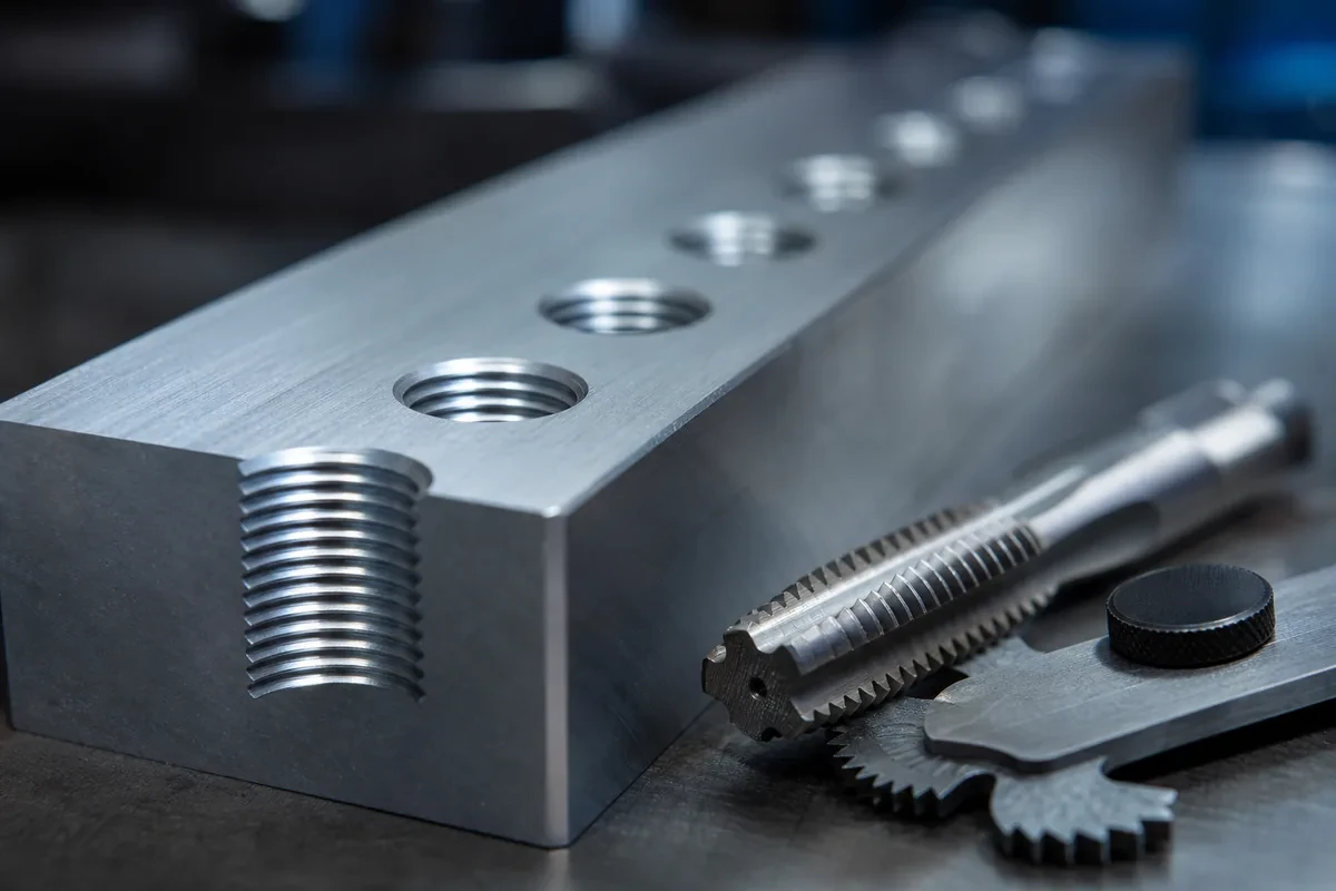
Thread callouts are the shortest notes on a drawing and among the most consequential. "M4" with no further detail has produced more scrap, more torque-test failures and more assembly arguments than any tolerance block.
This is what a thread specification needs, how the machining method changes the result, and where threads fail in practice.
A usable callout has five parts:
On a drawing with twenty threaded holes, a table is clearer than twenty callouts, and less likely to contain an inconsistency.
| Cut (tapped) | Roll-formed | |
|---|---|---|
| Pilot hole | Nominal minus pitch (M4 → Ø3.3) | Larger, specific to the form (M4 → ~Ø3.65) |
| Material | Removed | Displaced — grain flows along the thread |
| Strength | Baseline | Typically 20–30% stronger in fatigue |
| Speed | Faster for small quantities | Faster in production, needs specific tooling |
| Best for | General work, hard materials, large sizes | Ductile metals, thin walls, high-volume |
The practical risk is a mismatch: a drawing that calls for roll-formed threads but specifies a cut-thread pilot hole produces a hole that is too small, and the forming tap will either break or strip. Conversely, a roll-form pilot used with a cutting tap gives a thread that is loose and weak.
If you do not care which method is used, say nothing and accept the shop's default — usually cutting. If you do care, specify the method and let the shop choose the pilot hole.
A blind hole has three depths: drill depth, usable thread depth, and the depth the fastener actually needs. They must satisfy a simple inequality — the fastener must engage enough thread without bottoming out.
Rules of thumb for steel and aluminum:
A common error is specifying "M4 × 8 deep" and expecting a 10 mm bolt to sit flush. The thread stops at 8 mm, the bolt engages 8 mm, and if the hole is 8 mm deep overall the bolt bottoms on the drill point and the joint never closes.
In sheet metal and thin-walled parts, a cut thread has too few engaged turns to hold. Three options exist:
For machined parts, a threaded insert (helical or key-locking) is the standard solution where the base material is too soft or the thread will be serviced repeatedly — aluminum assemblies that are taken apart more than a handful of times benefit from inserts simply because aluminum threads wear.
A 6H internal thread with a 6g external fastener gives a normal clearance fit. Specifying 6H on a thread that must be sealed, or 5H on a thread that must assemble freely, produces either leakage or galling. For threaded joints that see vibration, a tighter class plus a thread-locking method is usually better than relying on torque alone.
Hand-tapped threads in a shop with a drill press can be a degree or two off perpendicular. Over a 10 mm depth that is enough to make a bolt bind, and it is invisible on a go/no-go gauge. Machine-tapped threads in a single setup do not have this problem — one more reason to keep threaded features in the same setup as their reference face.
Where a thread starts at a cast or machined surface, the first thread is often incomplete. A chamfer of roughly one pitch at the entry removes the partial thread and lets the fastener start cleanly. Without it, cross-threading during assembly is common.
Anodize, plating and powder coat all reduce the effective thread size. A 6H thread that was correct before anodizing may not accept a 6g bolt afterwards. Either mask the threads, specify the thread to be cut after coating, or use a coating that does not build in the thread — and say which on the drawing.
Stainless-on-stainless threaded joints gall, particularly at assembly speed. The remedy is a lubricant, a different alloy pair, or a thread insert. This is a design decision, not a machining defect, and discovering it during assembly is expensive.
Go/no-go gauges are the standard check: the GO gauge must enter the full thread, the NO-GO must not enter more than a specified number of turns. This confirms the thread is within its class — it does not confirm depth, perpendicularity or the condition of the first thread.
If thread integrity matters functionally, add a torque test or a pull-out test on a sample. A go/no-go gauge will pass a thread that strips at half the rated torque, because it measures form, not strength.
None — specify the thread and let the shop choose the pilot. If you must state it, remember that a cut M4 uses Ø3.3 and a roll-formed M4 uses roughly Ø3.65.
Thread depth equal to 1.5–2× diameter in aluminum, plus 2–3 pitches of runout, plus drill point allowance. For M4 in aluminum, a 6–8 mm thread in a 10 mm deep hole is typical.
No. A tap cannot cut to the very bottom, and a forming tap needs even more clearance. Design for a few pitches of incomplete thread and specify the usable depth.
They are stronger in fatigue and faster at volume, but they require a specific pilot hole and ductile material. In hard or brittle materials, cutting is the correct choice.
Anodize builds 5–50 µm per surface depending on type, which reduces the thread's effective size. Mask the threads, cut them after coating, or specify a looser class before coating.
An insert is a separate threaded component installed into the parent material. It exists because the parent material cannot hold a thread well enough, or because the thread will be serviced many times.
| Type | How it works | Best for |
|---|---|---|
| Helical (wire) insert | A coiled wire forms the thread in a tapped hole | Repairing damaged threads; protecting soft alloys |
| Key-locking insert | Solid bushing with keys driven into the parent material | High vibration, aerospace, threads that must not back out |
| Press-fit / broach insert | Knurled or splined body pressed or pulled into a hole | Plastics and thin sheet; fast installation |
| Heat-set insert | Installed with heat into thermoplastic | Moulded and 3D-printed plastic housings |
Three situations where an insert is the right answer rather than a workaround:
Two caveats matter at the drawing stage. First, an insert needs a larger hole than the thread it replaces, so wall thickness must allow for it — a boss designed for an M4 thread may be too small for an M4 insert. Second, an insert adds an operation and a component, so it should be specified deliberately rather than discovered when the first thread strips.
For machined parts that will see assembly and disassembly in the field, specifying inserts on the load-bearing threads is usually cheaper than the warranty cost of stripped aluminum threads.
State size, pitch, class, depth and method. Give the thread enough engagement without bottoming the fastener. Chamfer the entry, mask threads before coating, and keep threaded features in the same setup as their reference face. It takes one extra line on the drawing and prevents the most common assembly failure in machined parts.
We tap, thread-mill and install inserts as part of the machining flow, and we flag thread callouts that will not survive the specified coating. See our machining capabilities or send a drawing and we will review the thread table with you.
