


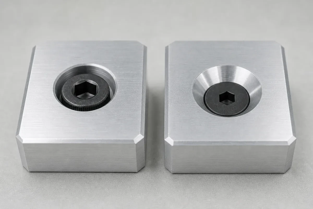
Counterbore and countersink are the two ways to make a screw head sit below a surface, and they are not interchangeable. One gives you a flat seat with a shoulder, the other a conical seat that self-centres. Choosing the wrong one produces a joint that loosens, a head that sits proud, or a hole that cannot be deburred.
The distinction is mechanical, not cosmetic, and it is decided by the fastener you have already chosen.
Counterbore — a flat-bottomed cylindrical recess with a shoulder at the bottom. It accepts a socket head cap screw (SHCS) or a hex bolt, whose head is cylindrical with a flat underside. The shoulder carries the clamping load and squares the head to the surface.
Countersink — a conical recess, typically 82° for inch fasteners and 90° for metric. It accepts a flat head or oval head screw, whose underside is a matching cone. The cone centres the screw and distributes load over the annular contact area.
| Counterbore | Countersink | |
|---|---|---|
| Fastener | Socket head cap screw, hex bolt | Flat head / oval head screw |
| Seat geometry | Cylindrical, flat shoulder | Conical, 82° or 90° |
| Depth control | Set by the tool stop, easy to measure | Set by the cone meeting the surface, sensitive to hole diameter |
| Centring | Needs the pilot hole to be accurate | Self-centring within limits |
| Typical use | Structural joints, thick sections | Flush cosmetic surfaces, thin sheet |
| Tool | Counterbore with interchangeable pilot | Countersink, single or multi-flute |
A socket head cap screw has a head with a 90° corner between the cylindrical side and the flat bearing face. Drop it into a conical hole and it contacts the cone on a line, not a face — the joint looks assembled but the head is bearing on an edge, and under vibration it works loose or cracks the cone.
A flat head screw has a conical underside. Put it in a counterbore and the cone bears on the flat shoulder on a circle, leaving the head standing proud of the surface by the depth of the cone. On a cosmetic panel that is immediately visible; on a structural joint it means the screw is preloaded against a line contact instead of a face.
The rule is therefore simple: match the seat to the head. The interesting engineering is in the cases where the standard geometry does not work.
The counterbore depth plus the material thickness must leave enough engaged thread. A common error is a counterbore deep enough that only three threads remain in a 6 mm plate. The screw holds, until it does not.
Rule of thumb: engagement of 1.5× diameter in steel and 2× diameter in aluminum, measured from the bottom of the counterbore.
A counterbore for an M6 SHCS is Ø11 mm. In a part with a 12 mm wide boss, that leaves 0.5 mm of wall — which will deform when the screw is torqued. Either widen the boss or move to a smaller fastener.
The counterbore has a small radius at the bottom where the tool meets the shoulder. Standard cap screws have a matching fillet, but cheap fasteners sometimes do not, and the head then rocks on the radius instead of seating flat. If the joint is critical, specify the fastener standard.
Inch flat head screws are 82°, metric are 90°. Mixing them produces a line contact that looks acceptable and is not. This happens most often when a part designed in the US is made in Asia and the drawing omits the angle.
Always dimension the angle and the head diameter, not just "csk for M5".
In 1.5 mm sheet, a countersink for an M4 flat head removes most of the material at that point. The remaining section is a knife edge that tears under load. The correct answer in sheet metal is a dimple or a punched extruded hole, not a countersink — and the drawing should say so.
A countersunk hole cannot be deburred with a standard tool without damaging the cone. The burr at the minor diameter has to be removed from the other side, or controlled by the drilling sequence. This is a real cost in parts with many countersunk holes.
Both features are usually called out with a positional tolerance, and both are more sensitive than designers expect:
Typical drawing values: ±0.1 mm for counterbores in a general tolerance block, and a true-position callout of Ø0.2 mm for anything that must align with a mating part.
On a CNC mill, both are single operations with a dedicated tool, so the difference is small. The cost appears in three places:
| Factor | Counterbore | Countersink |
|---|---|---|
| Tool changes per hole | One (pilot + bore in one tool) | One |
| Cycle time per hole | Slightly longer (plunge and retract) | Faster |
| Inspection | Depth gauge, simple | Go/no-go on cone diameter, fussier |
| Deburring | Straightforward | Difficult without damaging the cone |
In sheet metal the answer flips: countersinking is a secondary operation or a punch feature, while a counterbore is usually impossible. That is why sheet metal parts use flat head screws with dimpled holes and machined parts use cap screws with counterbores.
A counterbore is usually blind: it has a floor, which sets the screw's insertion depth and traps chips if the floor is not cleaned. A through counterbore — a counterbore that breaks into a larger cavity — is used when chips must escape or when weight matters, and it is dimensioned differently because there is no floor.
The distinction matters in a deep pocket: a blind counterbore at the bottom of a pocket may be impossible to machine without an extension tool, while a through feature can be cut from the other side.
There is also a third option that designers forget. If the head does not need to sit below the surface, a plain clearance hole with a flat washer costs less than either feature, gives a larger bearing area, and tolerates position error better. Counterbores and countersinks exist to hide a head or to guarantee a flush face; if neither is required, a washer is the cheaper engineering answer.
A counterbore is checked with a depth micrometer or a depth gauge, plus a pin or bore gauge for diameter. Both are quick, and both can be done at the machine.
A countersink is harder. The cone diameter where it meets the surface is the functional dimension, and it depends on both the tool depth and the hole diameter — so a correct depth with an oversized pilot gives an oversized cone. The practical check is a go/no-go gauge on the cone diameter, or a visual check against a known-good part where the feature is cosmetic.
This is the reason a drawing should dimension a countersink by its major diameter rather than by depth: diameter is what the fastener contacts and what can be gauged, while depth is a machine setting that produces the diameter only if the hole is right.
No. The head will stand proud by the height of the cone and bear on a line rather than a face. If you need flush mounting, use a countersink.
It will physically fit, and it is wrong. The cylindrical head contacts the cone on an edge, preload is unpredictable, and the joint loosens under vibration. It also looks like a mistake because it is one.
A shallow counterbore whose only job is to create a flat, perpendicular seating surface — typically on a casting or a rough surface. It has no depth requirement beyond cleaning up the surface. It is dimensioned by diameter and "spotface only".
Head height plus 0.2–0.5 mm clearance, so the head sits below the surface without the shoulder bottoming on the fillet. Too shallow and the head stands proud; too deep and you lose thread engagement.
Counterbore with a cap screw, because the flat shoulder gives a stable preload face. A countersunk joint relies on friction at the cone and is more sensitive to relaxation.
Cap screw or hex bolt: counterbore. Flat head screw: countersink. Match the angle (82° inch, 90° metric), dimension depth to the shoulder, and check that the bore does not eat the wall.
In sheet metal, neither is usually right — use a dimple. In thick sections, a spotface may be all you need. The general rules for hole and feature design sit alongside the rest of our DFM checklist, and if the holes carry threads, the depth and class conventions are in the threaded holes guide.
