


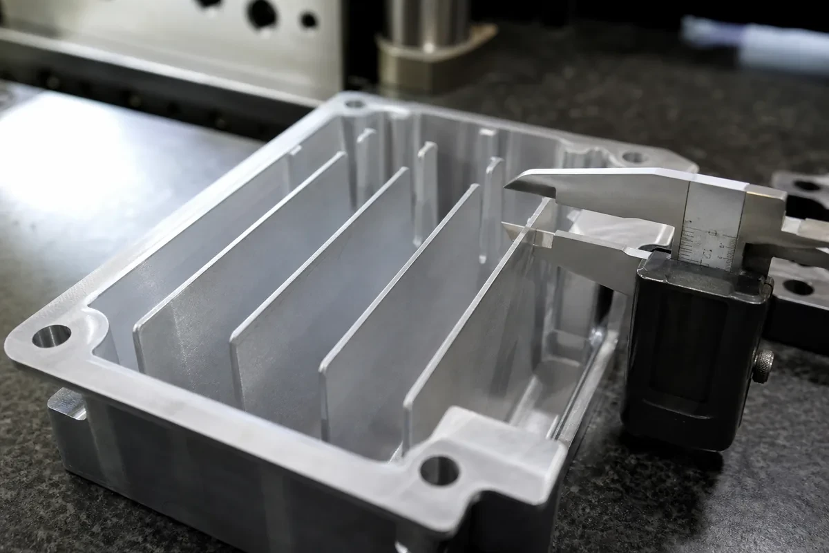
Every machined part has a point where it stops being rigid enough to cut cleanly, and that point is not a single number. It depends on the material, the height of the wall, whether the wall is supported at one edge or four, and what tolerance the drawing asks for. Designers who ask "what is the minimum wall thickness" usually get an answer that is either too conservative to be useful or too optimistic to be safe.
This guide gives the practical ranges, explains why the number moves, and shows the four cases where a wall that looks fine on a drawing fails at the machine.
For a machined pocket or a standing wall, these are the ranges that machine reliably at normal tolerances:
| Material | Practical minimum wall | Notes |
|---|---|---|
| Aluminum (6061, 6082) | 0.8 mm (0.03 in) | Down to 0.5 mm on small parts with light finishing passes |
| Brass, copper alloys | 0.8 mm | Free machining, but thin sections deflect under clamping |
| Mild and alloy steel | 1.0 mm | Higher cutting forces than aluminum |
| Stainless (304, 316) | 1.2 mm | Work hardening makes thin walls worse |
| Titanium (Grade 5) | 1.5 mm | Chatter and heat dominate below this |
| Engineering plastics (POM, PEEK) | 1.0 mm | Deflection and melting, not strength, limit it |
Two rules sit above that table. First, the minimum applies to a wall's **height-to-thickness ratio**, not its thickness alone: a 20 mm tall wall at 1 mm thick is 20:1 and will chatter, while a 5 mm tall wall at the same thickness is fine. Second, the minimum roughly doubles if the wall must hold a tolerance tighter than ±0.05 mm, because the wall moves as the material is removed around it.
A thin wall behaves like a cantilever. Push a 0.8 mm aluminum wall with a 10 mm end mill and it deflects away from the cutter, so the tool cuts less than programmed. As the wall springs back, the finished thickness is over-size in the middle and correct at the base — a bow shape that no amount of inspection at the top edge will reveal.
The workaround is a finishing pass with a small radial depth of cut and a sharp tool, sometimes from both sides. That costs time, and it is why a 0.8 mm wall often quotes at twice the price of a 2 mm wall with identical geometry.
Rolled plate carries internal stress. Machine a pocket into one side and the balance changes; the part bows. On a thin wall this shows up as a banana curve after the part comes off the fixture, and it is the most common reason a part that measured correctly on the machine fails at final inspection.
The fix is either stress-relieved stock (cast tooling plate, or T651 aluminum which is stretched after quenching), or a process that removes material from both sides in balanced amounts. Neither is free.
A vise closes on a thin wall and closes it slightly. Cut the part, release the vise, and the wall springs back — but the machined face is now not where the tool left it. On a 0.8 mm wall, vise pressure alone can move the surface by 0.03–0.08 mm.
Low-pressure fixturing, vacuum chucks, or potting the part in a low-melt alloy all solve it. Designers rarely see this cost, but it is real and it appears in the quote.
Below a certain stiffness, the wall resonates. Chatter leaves a rippled surface, destroys tool life, and can crack the wall outright. The onset is governed by the height-to-thickness ratio and by how the wall is supported at its ends. A wall tied into two perpendicular ribs behaves far better than the same wall standing free.
A heat-sink style fin, 25 mm tall and 1 mm thick, machined from aluminum. At 25:1 the fin will sing. The standard remedy is to machine it in steps with a support web left in place, then cut the web away last — an extra operation the drawing does not mention.
A 3 mm floor under a 20 mm deep pocket is not a wall problem, it is a floor problem: the floor deflects upward as the tool pushes down, and the last pass leaves a floor that is thin in the middle. If the floor also carries a seal or a bearing, the deflection becomes a functional failure.
A Ø8 H7 bore in a 1 mm wall is a contradiction. The wall cannot resist boring forces, and the finished bore will be oval within the wall's elastic range. Either thicken locally around the bore or accept a looser fit.
Two pockets machined from opposite faces leave a wall in the middle. That wall is unsupported at the top and bottom, and it is the weakest geometry in the part — worse than a free-standing wall of the same thickness, because the tool approaches from both sides and each pass moves it.
Wall thickness is one of the strongest cost drivers in machining, and not in a straight line. On a 100 × 80 × 30 mm aluminum housing at 50 pieces:
| Wall thickness | Relative cycle time | Relative price |
|---|---|---|
| 3 mm | 1.0 | 1.0 |
| 2 mm | 1.15 | 1.1 |
| 1.2 mm | 1.4 | 1.3 |
| 0.8 mm | 2.0+ | 1.6–1.9 |
The jump below 1 mm is not linear because the process changes: light finishing passes, a support fixture, and often a second inspection after the part settles. That is the point where a design decision becomes a purchasing decision.
The same thickness means something different in sheet than in a machined block. A 1 mm sheet wall is the whole part, not a feature cut into solid material, so it does not have a base to conduct heat away or a mass to damp vibration. What limits sheet is buckling and dent resistance, not cutting forces.
Practically: a 1 mm aluminium sheet panel is stiff enough for a cover and not stiff enough for a load-bearing side. The fix is a rolled edge, a hem, or a swage — not a thicker gauge. That is why sheet designs use formed features where machined designs use ribs, and why a design converted from machining to sheet often needs more than a material change.
If a part is being converted in the other direction — sheet to machined — the wall that was fine at 1 mm formed will chatter at 1 mm machined over the same height, because the machined version loses the stiffening the forming gave it.
Yes, on a small part, with a sharp tool, light passes, and a fixture designed for it. The wall will not hold a tight tolerance and it will not survive handling without care. If the wall is structural, 0.8–1.0 mm is a better target.
Yes, and the comparison is worth making: printing can produce 0.4 mm walls in some processes but with much lower strength and worse surface. If the wall is thin because the part is a shell, printing may be the cheaper route. If it must hold tolerance or carry load, machining at 1 mm is usually the right answer.
Not necessarily. The cost is driven by the wall's aspect ratio and by how much support the fixture needs, not by the part's overall size. A 20 mm cube with 0.6 mm walls is harder than a 200 mm plate with a 1.5 mm rib.
Realistically ±0.05 mm on thickness and ±0.1 mm on position, assuming a stable fixture and stress-relieved stock. Promising ±0.02 mm on a wall that thin invites a failed first article.
Dimension the two faces with their positions and let thickness be the result. A direct thickness dimension is hard to measure on a finished part and tends to be verified with a caliper at one point, which hides the bow.
Aluminum: 0.8 mm. Steel: 1.0 mm. Stainless: 1.2 mm. Titanium: 1.5 mm. Those are starting points for walls under 15:1 height-to-thickness, at general tolerances, with a fixture planned for the job.
Push below them only when the wall is short, supported at more than one edge, or free to carry a loose tolerance. If the wall must do all three of those things and be thin, the cost is not a percentage — it is a different manufacturing plan, and it should be quoted as one. The rest of the design rules that move machining cost are collected in our DFM checklist, and the tolerance side of the same trade-off is covered in the tolerance guide.
