


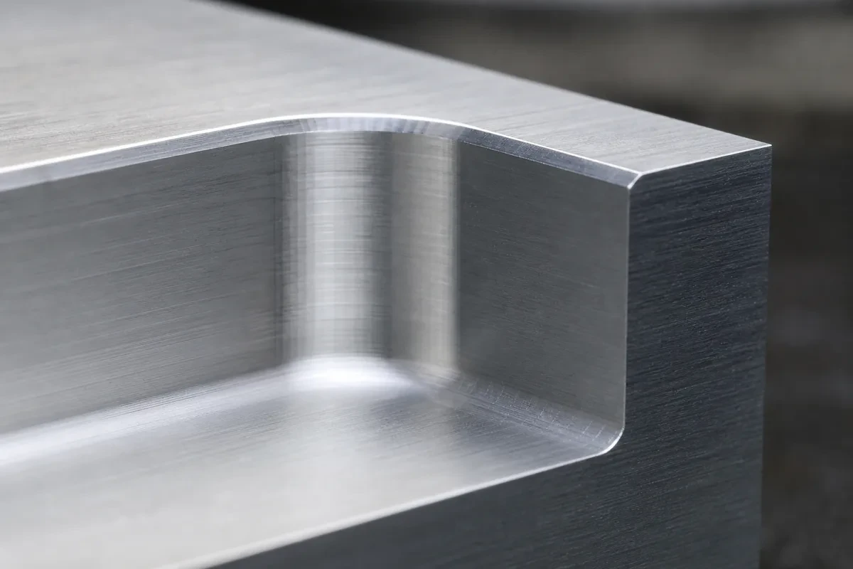
Every machined part needs its sharp edges dealt with. The two options are a chamfer (a flat angled cut) and a fillet (a rounded transition), and the choice affects strength, cost, assembly and how the part feels in the hand. Most drawings specify one without saying why, which is how a part ends up with a fillet where a chamfer would have been cheaper and stronger.
Chamfer — a straight cut at an angle, usually 45°, removing the sharp corner. It is dimensioned either as legs (1 × 45°) or as a distance and an angle (0.5 × 30°).
Fillet — a radius blending two surfaces. It is dimensioned as a radius (R3) and is produced either by a corner-radius end mill or by a ball nose in a separate pass.
The mechanical difference is stress concentration. A sharp internal corner concentrates stress by a factor that depends on the radius: at R0.5 the factor can be 2.5–3, at R5 it can be below 1.5. A chamfer does not reduce stress concentration at all — it only removes the burr and the sharp edge.
If a part carries load through a corner, a fillet is structural. Three cases where specifying a chamfer is a design error:
At the same time, a fillet that is too large creates its own problem: it reduces the flat area available for a mating part, and on a thin wall it can remove so much material that the section becomes weak in a different way.
Chamfers exist mainly to guide and protect:
| Chamfer | Fillet | |
|---|---|---|
| Tool | Chamfer mill or spot drill — often already in the machine | Corner radius or ball nose end mill, often a separate tool change |
| CAM | Simple 2D contour | 3D path on curved intersections |
| Cycle time per edge | Seconds | Tens of seconds, more on complex geometry |
| Inspection | Visual or a quick gauge | Radius gauge, or profile projector on critical parts |
| Typical added cost | Near zero | 5–15% on a part with several fillets |
The cost gap is why "deburr all edges" is such an expensive note. It forces a hand operation on every edge, whereas "break edges 0.3–0.5" can be done by a chamfer tool in the program.
A pocket's internal corner radius must be at least half the cutter diameter you want the shop to use, plus clearance. A 1 mm radius forces a Ø2 mm cutter at whatever depth the pocket is — slow, fragile, and prone to chatter. A 5 mm radius lets the shop use a Ø10 mm cutter.
Rule: make the corner radius at least one third of the pocket depth. It is the single highest-leverage change in most DFM reviews.
Breaking an external corner with a chamfer is cheap and usually enough. A fillet on an external corner is for feel (hand-held parts), for coating adhesion (sharp edges coat thin), or for fatigue.
Two fillets intersecting produce a complex surface that is slow to machine and hard to inspect. If a drawing has a fillet running around three faces, expect the shop to ask whether a constant chamfer would do the same job.
0.2–0.5 mm is the normal range for a "break sharp edges" note. Larger than 1 mm starts to be a functional feature and should be dimensioned explicitly, because it changes the part's effective size.
Sharp edges are a coating problem. Paint and powder coat pull away from a sharp corner, leaving a thin film that fails first. Anodize builds less on a sharp edge for the same reason. A 0.3–0.5 mm chamfer or a small fillet gives the coating something to hold.
On parts that will be anodized and handled, a 0.5 mm chamfer is often the difference between a finish that looks even and one that shows bright edges after a month of use.
Sheet metal has its own conventions, and importing a machining rule into a sheet design causes problems. A chamfer on a laser-cut edge is a deburring operation that is usually unnecessary — laser edges are clean enough to handle. A fillet on a bend is not a feature at all: the bend radius is set by the tooling and the material, not by a drawing callout.
What sheet parts do need is attention to the corners — the intersection of two bends, where material stretches and can tear. A relief notch there is functional, and it is often missing from drawings converted from a machined design.
Castings invert the logic. A casting already has draft and generous radii from the mould, so the machined features on it are the ones with sharp edges. Those are the edges that need a chamfer, and they are also the edges where a coating will be thinnest.
Some chamfers are not edge treatment at all — they are the feature. A 45° lead-in on a bore is what allows a shaft to enter without damage. A 30° chamfer on a shaft end is what lets it start into a seal without cutting it. A bevel on a weld prep is what creates the groove the weld fills.
In those cases the chamfer needs a tolerance and an inspection, and it must not be left to the "break sharp edges" note. A 0.3 mm deburring chamfer on a bore that needs a 1.5 mm lead-in is a functional failure that passes a visual check.
So the drawing has two kinds of chamfer, and they should not share a callout: cosmetic edge breaks, which can be a general note, and functional chamfers, which need size, angle and a tolerance just like any other feature.
No. A chamfer removes material at the corner and does not reduce stress concentration. If the corner carries load, it needs a radius.
Because they are faster and use tooling that is usually already in the machine. A fillet requires a specific cutter and a 3D toolpath, and on internal corners it limits the cutter size for the whole pocket.
A very small chamfer or radius, typically 0.1–0.3 mm, whose only purpose is to remove the burr and the sharp feel. It is not a functional feature and is usually covered by a general note.
Yes, for a different reason: a fillet reduces the stress concentration at layer boundaries and prints more reliably than a sharp internal corner. On machined parts the reason is mechanical, on printed parts it is also mechanical but the failure mode is delamination.
It is machinable with a Ø1 mm cutter, but only in shallow pockets and at a significant cost in time and tool breakage. Treat R0.5 as a specialist feature, not a default.
Use a chamfer to break edges, guide assembly, protect threads and prepare welds — it is cheap and almost always sufficient. Use a fillet where load turns a corner, where fatigue matters, or where a coating needs something to hold.
The expensive mistake is specifying a small fillet in a deep pocket: it forces a tiny cutter and multiplies cycle time. If you only change one thing on a drawing this week, make the internal corner radius at least one third of the pocket depth. The rest of the geometry rules are in our DFM guide, and the cost consequences of tight radii are covered in the tolerance breakdown.
