


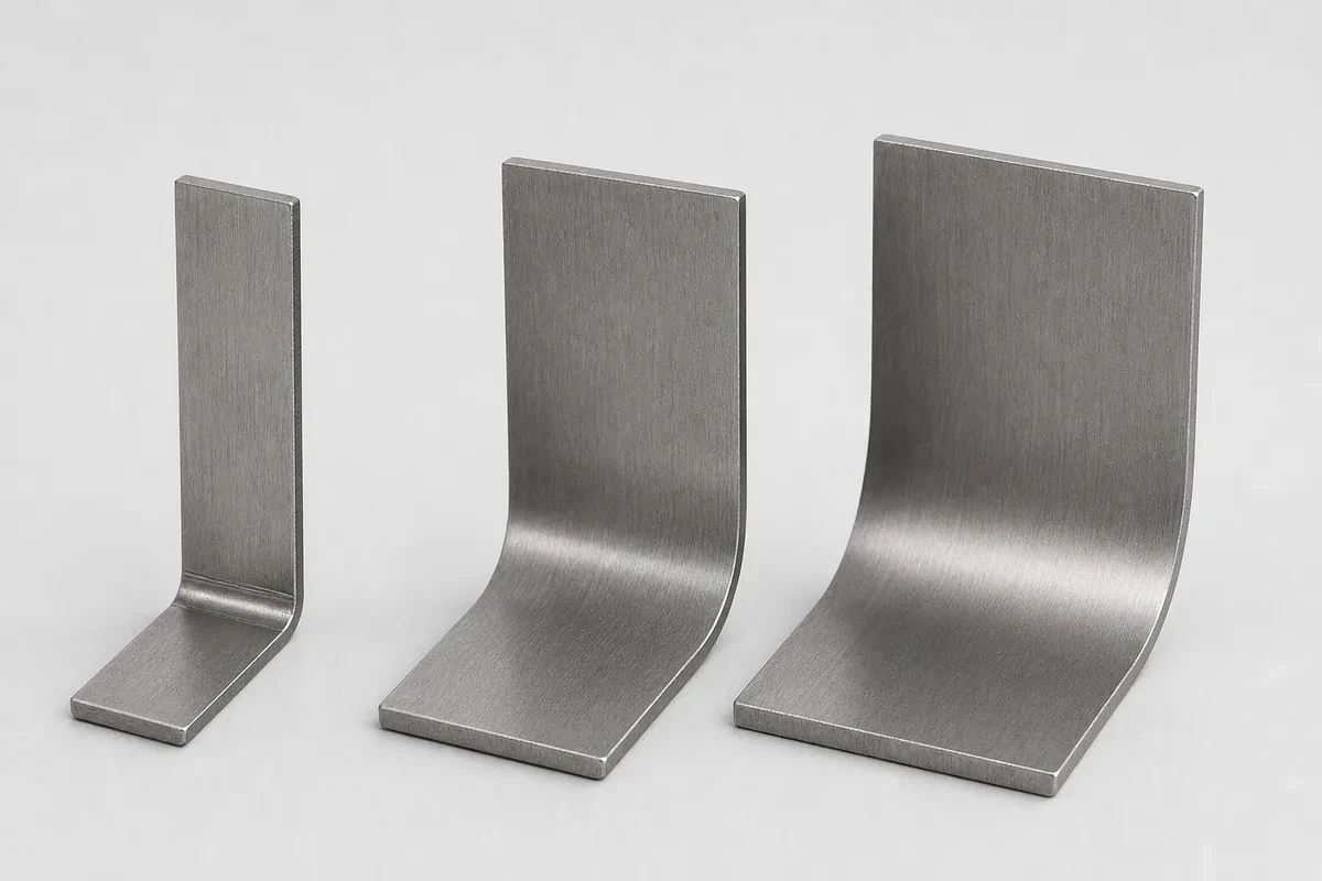
Every sheet metal bend has an inside radius, and that radius is not a cosmetic choice. Bend too tightly and the outer surface cracks, the part loses strength at the corner, and the flat blank length is wrong. Specify a radius with no relationship to the material thickness and the shop will either substitute its standard tooling radius or come back with a question.
This guide gives the working minimum bend radius by material, explains the grain-direction and hole-clearance rules that accompany it, and shows how the radius feeds into flat pattern calculation.
For most sheet metals, the minimum inside bend radius is expressed as a multiple of thickness T. For soft aluminum and mild steel, R = 1 x T is a safe default. Harder materials need more.
| Material | Minimum inside radius (soft / annealed) | Minimum inside radius (hard / temper) |
|---|---|---|
| Aluminum 5052-H32 | 1 x T | 1.5 x T |
| Aluminum 6061-T6 | 1.5 x T | 3–4 x T |
| Mild steel (DC01 / A36) | 0.5–1 x T | 1–1.5 x T |
| Stainless 304 (annealed) | 1 x T | 2 x T |
| Stainless 316 | 1 x T | 2 x T |
| Copper / brass (soft) | 0.5 x T | 1 x T |
| Galvanized steel | 1 x T | 1.5 x T |
| High-strength / spring steel | 2 x T | 4 x T or more |
So a 2 mm 5052-H32 bracket should not be drawn with an R0.5 inside radius. R2 mm is the practical minimum, and R2–3 mm is what most press brake tooling will naturally produce.
Bending stretches the outer surface and compresses the inner one. The outer fibre strain is approximately T / (2R + T). As R approaches zero, that strain approaches 100% — far beyond the elongation limit of any metal. The result is cracking along the outside of the bend, visible even on a sample coupon.
For a 2 mm sheet bent at R = 2 mm, outer strain is about 2/(4+2) = 33%. At R = 0.5 mm it is 2/(1+2) = 67%. Materials with low elongation (6061-T6 is around 8–12%) crack long before that; 5052-H32 (around 12–18%) tolerates the larger radius but not the sharp one.
Even when the part does not visibly crack, an over-tight bend leaves a work-hardened, thinned corner that is the first place a fatigue crack starts. This is why a bend radius is a functional dimension on brackets that see vibration.
Rolled sheet has a grain direction from the rolling process. Bending across the grain (bend line perpendicular to the rolling direction) distributes strain across many grain boundaries and allows a tighter radius. Bending with the grain (bend line parallel to rolling) concentrates strain along boundaries and can split the part at a radius that would otherwise be safe.
| Bend orientation | Effect on minimum radius |
|---|---|
| Perpendicular to grain (preferred) | Use the table values above |
| Parallel to grain | Multiply the minimum radius by 1.5–2 |
| 45° to grain | Intermediate; avoid for critical bends |
If a part has multiple bends in different directions, nest the flat blanks so the critical bends run across the grain. This is a nesting decision, not a drawing dimension, and it is worth noting on the RFQ when the material is marginal. Our sheet metal tolerances guide covers what else to specify.
On a press brake, the inside radius is largely set by the V-die opening, not by the punch tip. In air bending, the sheet only contacts the punch nose and the two die shoulders; the radius forms freely and is roughly 15–20% of the V opening. Bottoming (coining) forces the sheet against the punch and die and produces a radius close to the punch tip.
| V-die opening (for 2 mm mild steel) | Typical air-bend inside radius |
|---|---|
| 12 mm (6 x T) | R 1.8–2.4 mm |
| 16 mm (8 x T) | R 2.4–3.2 mm |
| 20 mm (10 x T) | R 3.0–4.0 mm |
| 25 mm (12 x T) | R 3.8–5.0 mm |
Practical consequence: if the drawing says R1 on 2 mm sheet, but the shop must use a 16 mm V-die to get the required tonnage and flange length, the part will come out at R2.5–3. Either accept the tooling radius or specify a bottoming operation, which costs more and needs dedicated tooling.
Most cost-effective drawings allow the shop to select the V-die and specify the inside radius as a range (e.g. R2–3) rather than a single number. See our cost reduction guide for the equivalent logic on machined features.
Material near a bend line deforms. A hole placed too close will stretch into an oval, and a slot will distort badly enough to miss its mating fastener. The standard rule:
Minimum distance from bend line to hole edge = 2 x T + R (some shops use 2.5 x T + R for safety).
| Thickness | Inside radius | Minimum hole-to-bend distance |
|---|---|---|
| 1 mm | R1 | 3 mm |
| 2 mm | R2 | 6 mm |
| 3 mm | R3 | 9 mm |
| 5 mm | R5 | 15 mm |
When a hole must be closer, the fix is a bend relief — a small notch cut at the ends of the bend line that isolates the bent region — or punching the hole after bending. Both add an operation, so it is cheaper to move the hole on the drawing. For a related assembly constraint, see our tapped hole guide.
The sheet must sit on both die shoulders to form a clean bend. A practical minimum straight flange is roughly 3 x T + R, or about half the V-die opening. A 2 mm sheet on a 16 mm V-die needs at least an 8–10 mm flange. Shorter flanges either slip into the die or require special tooling.
Bending does not change the length of the neutral axis, but it does change the developed (flat) length. The bend allowance is the arc length of that neutral axis:
BA = (π/180) × bend angle × (R + K × T)
where K is the K-factor, the fractional position of the neutral axis through the thickness. A larger inside radius increases BA directly. For a 90° bend in 2 mm sheet going from R2 to R4, BA increases by roughly 3 mm — enough to shift every downstream hole position if the flat pattern is not recalculated.
This is why changing a bend radius late in a project is not a cosmetic edit. Our K-factor guide works through the calculation in full, including how to derive K from a test bend.
A bend does not stay at the angle you formed it: the elastic portion of the strain recovers when the punch retracts, and the part springs open by a few degrees. Springback grows with the ratio of inside radius to thickness. A tight R0.5 bend on 1 mm sheet plastically deforms most of the cross-section and springs back perhaps half a degree; a generous R6 bend on the same sheet leaves a large elastic core and can spring back three degrees or more.
| R / T | Typical springback (mild steel, 90° air bend) | Compensation approach |
|---|---|---|
| 0.5 – 1 | 0.5 – 1° | Standard overbend |
| 2 – 3 | 1 – 2° | Overbend, verify on first article |
| 5 – 10 | 3 – 6° | Overbend plus angle check, or bottoming |
| Stainless / high-strength | 2x mild steel | Dedicated tooling or CNC angle correction |
The practical consequence is that a large radius is not automatically the "safe" choice. It protects against cracking and allows cheaper tooling, but it makes the final angle less predictable, and the shop must overbend further to hit the drawing. On a bracket where the flange angle determines assembly fit, a moderately tight radius with a well-characterized overbend can be easier to hold than a generous one.
Bottoming or coining reduces springback because the sheet is plastically compressed through the bend region, but it needs higher tonnage and dedicated tooling. Air bending with a CNC press brake and in-process angle measurement is the modern alternative. Either way, note that a radius change late in a project alters both the flat pattern and the required overbend — two corrections, not one. Our K-factor guide covers the flat-pattern half of that relationship.
About R2 mm for 5052-H32 (1 x T) and R3–8 mm for 6061-T6 depending on temper. Always check the specific grade and temper rather than assuming "aluminum is soft".
Not without cracking the outer surface. Zero radius implies close to 100% outer-fibre strain, far beyond the elongation of any common sheet metal. Even a visually sound sharp bend leaves a thinned, work-hardened corner.
The neutral axis arc length grows with the inside radius. A larger R increases the bend allowance, so the flat blank must be longer. Changing R without recalculating the flat pattern shifts hole positions.
At least 2 x T + R from the bend line to the hole edge, and 2.5 x T + R where the hole position is critical. Closer holes distort into ovals; use a bend relief or punch after bending instead.
For cost-sensitive parts, a range (e.g. R2–3 on 2 mm sheet) lets the shop use standard V-die tooling. An exact radius may require bottoming or dedicated tooling and adds cost without improving function.
Bend radius is one of a handful of sheet metal parameters that ripple into tooling, flat pattern, and assembly fit at the same time. Settling it against the actual material grade before the drawing is released avoids most first-article surprises.
