


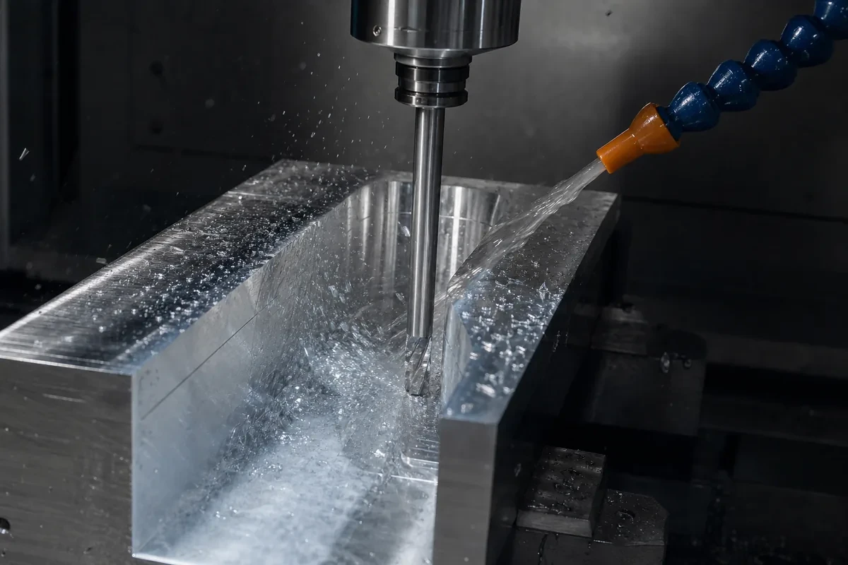
A 6 mm end mill will cut a 12 mm deep pocket all day long. Ask it to cut a 60 mm deep pocket with the same width and the job changes completely — not because the machine lacks travel, but because the tool has become a long, flexible cantilever with nowhere to put its chips. Depth-to-diameter ratio, usually written L/D, is the number that separates a routine pocket from a difficult one.
This guide gives the practical L/D limits, explains what fails as the ratio increases, and covers the design changes that make deep pockets cheap.
For a standard flat-bottom end mill in aluminum or steel, keep L/D at or below 3 for a normal quote. Up to 5 is achievable with reduced parameters. Beyond 6, expect a specialized strategy, longer cycle time, and a conversation about tool access.
| L/D (flute length / diameter) | Difficulty | What changes |
|---|---|---|
| ≤ 2 | Routine | Full slotting passes, standard feeds |
| 3 | Comfortable | Normal adaptive roughing |
| 4–5 | Reduced parameters | Lighter radial engagement, slower feed, more passes |
| 6–8 | Specialized | Necked tools, trochoidal paths, high-pressure coolant, chip evacuation plan |
| > 8 | Process change | Plunge milling, EDM, or split the part into two pieces |
Here L is the flute length below the holder, not the nominal pocket depth — the tool must reach the floor with some clearance, and the holder itself needs to clear the top of the part.
Cantilever deflection grows with the cube of overhang and inversely with the fourth power of diameter. Doubling the reach at the same diameter gives roughly eight times the deflection. A 6 mm tool at 36 mm overhang bends enough under a normal cutting load to leave a tapered wall, an out-of-tolerance floor, or a chatter-marked finish that no amount of spring passing fully removes.
This is the same stiffness limit that governs thin walls and small internal corner radii. Deep pockets are simply the third place it shows up.
In a shallow pocket, chips escape upward and away. In a deep one they recirculate, get recut, weld to the cutting edge, and eventually pack the flutes. Recutting chips is the main cause of poor surface finish and sudden tool failure in deep pockets — often more important than deflection.
Through-spindle coolant, air blast, or a peck-cycle that periodically retracts the tool to clear chips all help. None of them can be added after the fact if the pocket geometry gives chips nowhere to go.
Long tools have low natural frequencies. Once the tooth-engagement frequency lines up with the tool's resonance, the system self-excites and leaves a characteristic wavy pattern on the pocket wall. Variable-pitch end mills, reduced radial engagement, and tuned spindle speeds suppress it, but the underlying fix is a shorter or stiffer tool.
| Tool diameter | Comfortable depth (3xD) | Practical max (5xD) | Corner radius left |
|---|---|---|---|
| 3 mm | 9 mm | 15 mm | R1.5 |
| 6 mm | 18 mm | 30 mm | R3 |
| 8 mm | 24 mm | 40 mm | R4 |
| 10 mm | 30 mm | 50 mm | R5 |
| 12 mm | 36 mm | 60 mm | R6 |
| 16 mm | 48 mm | 80 mm | R8 |
The last column is the constraint that catches designers. A pocket with R1 internal corners requires a 2 mm cutter, which can only reach about 6–10 mm. A 40 mm deep pocket with R1 corners is not a milling problem — it is a design contradiction. Either the radius grows, or the process changes.
Instead of slotting at full width, the tool takes a small radial step (typically 5–15% of diameter) at full axial depth, following a circular path that keeps the engagement angle constant. Cutting load stays steady, heat goes into the chip rather than the tool, and chip evacuation improves. This is the default strategy for deep pockets on modern machining centres.
A tool with a reduced-diameter shank behind a short flute section reaches deep without the whole length rubbing against the wall. It costs more than a standard end mill but is far stiffer than a full-flute long-reach tool. Specify it for L/D above 5.
The tool cuts straight down like a drill, overlapping plunges to remove material. Radial forces are low, so deflection is minimal even at high L/D. It is slower in soft materials but often the only practical way to rough a very deep cavity on a machine without through-spindle coolant.
A few degrees of draft on the pocket walls allows a tapered end mill, which is dramatically stiffer than a straight tool of the same tip diameter. This is standard practice in mould and die work and is worth considering for any deep cavity where the walls do not need to be perfectly vertical.
Two shallow halves bolted or bonded together are frequently cheaper than one deep pocket. It also improves access for inspection and finishing. On housings, a separate cover plate is the obvious version of this.
| Material | Deep-pocket behaviour |
|---|---|
| 6061 aluminum | Forgiving; chip welding is the main risk, use polished flutes and coolant |
| 7075 aluminum | Similar, but thin floors can distort after roughing |
| Mild steel | Higher cutting force; reduce radial engagement |
| 304 / 316 stainless | Work hardening; never let the tool rub, keep chip load up |
| Titanium Grade 5 | Heat stays in the tool; low surface speed, high-pressure coolant essential |
| Inconel 718 | Extreme; very short tool life, expect L/D ≤ 2 in practice |
In titanium and nickel alloys, the honest advice is to design the pocket shallower. Tool life at high L/D in these materials is short enough that the quoted price reflects it — see our Inconel 718 machining guide for how quickly the cost multiplier grows.
Deep pockets are hard to measure. A standard caliper cannot reach the floor, and a CMM probe needs a long stylus that itself deflects. Plan for this on the drawing: specify floor thickness rather than pocket depth where possible, since thickness can be measured from the outside with a micrometer.
Wall taper and floor flatness are the two characteristics most likely to drift with L/D. If they are functional, say so — a shop will otherwise assume a general tolerance and use a light finishing pass that may not correct a deflected roughing pass.
The effective overhang is measured from the point where the tool is supported, not from the cutting tip. A cutter held in a worn collet with 40 mm of stick-out behaves like a much longer, less accurate tool than the same cutter in a shrink-fit or hydraulic holder gripped close to the shank. On deep-pocket work the holder is often the difference between a stable cut and chatter.
| Holder type | Typical runout | Suitability for high L/D |
|---|---|---|
| Standard ER collet (good condition) | 0.01–0.02 mm | Adequate to L/D ≈ 4 |
| Precision collet / nut | 0.005–0.01 mm | Good to L/D ≈ 6 |
| Shrink-fit | < 0.005 mm | Best; short gripping length allows deeper reach |
| Hydraulic chuck | < 0.005 mm | Best; also damps vibration |
Runout matters more as the tool gets longer because one flute ends up taking a disproportionate share of the cut. At 0.02 mm runout on a 3 mm cutter, the uneven chip load is significant; on a 12 mm cutter it is minor. The overloaded flute wears first, the cutting force becomes cyclic, and chatter follows.
Two practical habits help. Measure the actual stick-out and record it in the setup sheet rather than relying on the tool table's nominal value, and keep the holder as close to the workpiece as the pocket walls allow — a necked tool exists precisely so the holder can stay outside the cavity while the cutting portion reaches in. When a job is quoted with an unusually long tool, asking about the holder is a fair question; it often explains the price difference between two otherwise identical quotes. For more on the setup decisions that drive quoting, see our machining quote breakdown.
3:1 or less for routine work. 5:1 is achievable with lighter radial engagement and slower feeds. Above 6:1 expect necked tools, high-pressure coolant, and a noticeably longer cycle time.
Tool deflection grows with the cube of overhang, so a long cutter bends under load and leaves tapered walls or chatter. Chips also cannot escape, so they get recut and pack the flutes. Both problems worsen together.
The radius fixes the tool diameter, and the tool diameter fixes the reachable depth at a given L/D. A 40 mm deep pocket with R1 corners needs a 2 mm cutter at 20:1 L/D, which is not practical. Increase the radius to R3 or R6.
A toolpath that keeps the cutter at a small, constant radial engagement (5–15% of diameter) while cutting at full axial depth. It stabilizes cutting load, controls heat, and improves chip evacuation in deep pockets.
When L/D exceeds about 8, when the material is difficult to machine, or when inspection access is poor. Two shallow halves are often cheaper than one deep cavity and easier to finish and verify.
If a pocket on your drawing is deeper than it is wide by a factor of four or more, flag it before the RFQ goes out. A small radius increase or a few degrees of draft at the design stage is worth far more than any toolpath optimization later — see our DFM rules for the full checklist.
