


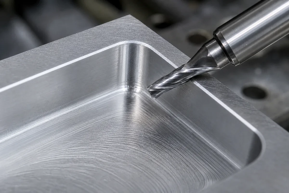
Ask a designer to draw a pocket and they will draw four sharp 90-degree corners. Ask a machinist to cut it and the first question is which end mill you are willing to pay for. An internal corner cannot be sharp with a rotating cutter: the tool has a radius, and that radius becomes the corner. Every internal corner on a CNC milled part is, by definition, a fillet.
That single geometric fact drives tool selection, cycle time, surface finish and cost more than most people expect. This guide gives the practical radius ranges, explains the depth-to-diameter relationship that quietly sets the real minimum, and shows what to put on the drawing so the shop does not have to guess.
For a standard pocket in aluminum or steel, specify an internal corner radius of at least 3 mm (0.125 in) if you want a normal quote. Smaller is possible, but it is never free.
| Specified internal radius | Tool it implies | Practical consequence |
|---|---|---|
| R6 mm or larger | 12 mm end mill or bigger | Fast, rigid, one roughing pass |
| R3 mm | 6 mm end mill | Comfortable default for most pockets |
| R1.5 mm | 3 mm end mill | Slower feeds, limited depth, higher tool cost |
| R0.5 mm | 1 mm end mill | Very slow, shallow passes, frequent breakage |
| R0 (sharp) | Not millable | Requires EDM, broaching, or a dogbone relief |
The rule of thumb: the corner radius should be at least one sixth of the pocket depth, and ideally larger. A 30 mm deep pocket with R1 mm corners is a part that will be quoted slowly, or declined.
An end mill is a cylinder. Sweep it around a 90-degree internal corner and the cutter centre follows an arc whose radius equals the tool radius. The material left in the corner is a quarter-circle of exactly that radius. There is no feed rate, no toolpath strategy and no controller setting that changes this; it is geometry.
External corners are different. A sharp outside edge is easy because the tool approaches from free space. This asymmetry explains why drawings that mix sharp external edges with sharp internal corners look perfectly reasonable in CAD but cannot be made as drawn.
The confusion usually comes from other processes. A laser-cut blank, a waterjet part, an injection moulded part or a wire EDM part can have near-sharp internal corners, because those processes do not use a rotating cylindrical tool. If a designer has spent more time on sheet metal or moulded parts than on milled parts, sharp internal corners feel normal. Our guide to the differences between moulding and machining covers where that assumption breaks down.
If the drawing says R2 and the shop uses a 6 mm end mill, the corner comes out R3. The part is out of spec even though every other dimension is correct. Conversely, if the drawing says R6 and the shop uses a 6 mm mill, the corner is R3 and it is still out of spec — too small a radius leaves a step where the mating part expects clearance.
This is why a corner radius callout is really a tool diameter callout. Writing "R3" tells the machinist "use a 6 mm cutter here", and that in turn constrains how deep they can cut.
Tool deflection scales with the cube of the overhang and inversely with the fourth power of the diameter. In plain terms, a long thin cutter is dramatically less stiff than a short thick one. A 6 mm end mill cutting at 3x diameter (18 mm) of flute length is routine; the same tool at 6x diameter (36 mm) needs reduced radial engagement, lighter passes and often a completely different strategy.
| Tool diameter | Comfortable max depth | Absolute max with care | Typical corner radius |
|---|---|---|---|
| 12 mm | 24–36 mm | 48 mm | R6 |
| 8 mm | 16–24 mm | 32 mm | R4 |
| 6 mm | 12–18 mm | 24 mm | R3 |
| 3 mm | 6–9 mm | 12 mm | R1.5 |
| 1 mm | 1.5–2 mm | 3 mm | R0.5 |
So a 25 mm deep pocket with R1 mm corners is contradictory: the radius demands a 2 mm cutter, but that cutter cannot reach 25 mm. The shop must either use a tapered or necked tool, switch to a different process, or ask you to change the design. Most of the "unexpected" cost on small-radius deep pockets comes from exactly this conflict.
For a deeper treatment of the related depth problem, see our article on minimum wall thickness, where the same stiffness limit shows up as wall deflection rather than corner radius.
Three costs compound:
A useful mental model: specifying R1 instead of R3 on a mid-size aluminum housing typically adds 15–40% to the milling time, and on hardened steel it can double it. Enlarging the radius is one of the highest-leverage DFM changes available — see our cost-reduction checklist for the other levers.
Sometimes a mating part has a square shoulder and the assembly really does need the pocket to seat fully. There are four standard solutions:
The shop extends the cutter slightly past the corner in each direction, leaving a small circular relief. The mating square corner now fits, and the pocket walls remain straight where they matter. Dogbones are cheap and are the default answer for a square insert in a milled pocket. They do require the designer to accept a visible relief, and they need to be called out explicitly — a shop will not add them unasked.
A single relief on one side of the corner, rather than both. Easier to program, slightly weaker in the corner region, and common on larger enclosures where one wall is non-critical.
Wire EDM produces a genuinely sharp internal corner with a small wire radius, but only on through-features in conductive material, and at a much higher cost per part. Broaching works for specific profiles. Both are viable for low volumes of hardened tooling components.
Usually the best answer. If the insert can carry an R3 chamfer or radius, the pocket can be cut with a 6 mm tool in one pass and the whole problem disappears. This is a conversation worth having before the drawing is released.
Four things remove ambiguity:
Tolerance on a corner radius deserves the same restraint as any other non-functional feature. Holding R3 ±0.05 requires inspecting a radius, which is slower and less repeatable than measuring a linear dimension. R3 ±0.2, or simply "R3 max / R2.5 min", is usually enough. Our tolerances guide explains which callouts actually drive inspection cost.
| Material | Effect on small internal radii |
|---|---|
| 6061 / 6082 aluminum | Forgiving; small cutters work well with good chip evacuation |
| 7075 aluminum | Similar, but thin corner sections can distort after roughing |
| Mild and alloy steel | Higher cutting force; deflection increases with smaller tools |
| 304 / 316 stainless | Work hardening; avoid rubbing in corners with light radial engagement |
| Titanium Grade 5 | Heat concentration in corners; small tools have very short life |
| POM, PEEK, G10 | Deflection and melting rather than tool wear set the limit |
In stainless and titanium, corner cleanup passes are where tools fail most often, because the cutter engagement angle spikes as it enters a corner. A constant-engagement toolpath (trochoidal or adaptive) keeps the load steady and is worth specifying for deep pockets in these materials.
Radius gauges, a CMM with a small probe, or an optical comparator all work, but a radius is inherently harder to verify than a diameter. On a production run, shops often verify the pocket width and the corner clearance with a gauge pin or a mating part instead of measuring the radius directly.
If the corner radius is functional — for instance it controls stress concentration at a loaded fillet — say so on the drawing. A functional radius gets measured; a cosmetic one gets a visual check, and treating them identically adds cost without adding confidence.
There is no hard minimum, but R0.5 mm is about the practical floor for milled metal parts, and it requires a 1 mm cutter, shallow depths and slow feeds. For a normal production quote, R3 mm is the sensible default. Anything below R1 should be treated as a deliberate cost decision.
Because the cutting tool is a rotating cylinder. The tool centre traces an arc, leaving a quarter-circle of material at every internal corner. Only non-rotating processes — wire EDM, broaching, laser or waterjet cutting, and moulding — can produce a near-sharp internal corner.
Usually the opposite. A larger radius reduces stress concentration at the corner. The concern is assembly clearance: a mating part with a square shoulder may no longer seat. That is solved with a dogbone relief or by radiusing the mating part, not by shrinking the pocket radius.
The radius determines the maximum tool diameter, and tool diameter determines how deep the cutter can reach before deflection becomes unacceptable. As a working rule, keep pocket depth below 3x the tool diameter for comfort, which means the corner radius should be at least one sixth of the depth.
Only if the radius is functional. A loose callout such as R3 ±0.2 or "R3 max" is enough for clearance features. Tight radius tolerances slow inspection and rarely improve fit, since the mating part is what actually determines whether assembly works.
If you are unsure whether a corner radius on your drawing will survive contact with a real end mill, send the model before releasing it. A five-minute DFM review at the design stage is considerably cheaper than a re-quote after the first article. For more on that process, see our DFM rules for machined parts.
