


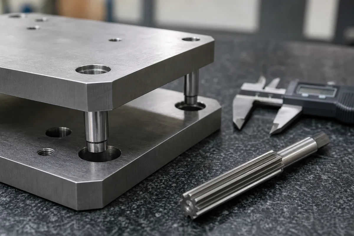
Dowel pins do one job: they put two parts back in exactly the same place every time they are assembled. They are not supposed to carry the load, and they are not supposed to be adjusted. That narrow job makes the hole tolerance surprisingly unforgiving — a dowel hole that is 0.01 mm off in size, or 0.05 mm off in position, can make an otherwise perfect assembly impossible to put together.
This guide covers the fits that actually work, why one hole should be tight and the other loose, and the positional tolerance that matters more than the diameter callout.
For a steel dowel pin locating two machined parts, use H7/m6 for the press-fit hole and H7/h6 (or H7/g6) for the slip-fit hole — and never press-fit both holes in the same assembly.
| Fit | Hole | Pin | Result | Typical use |
|---|---|---|---|---|
| Press / interference | H7 | m6 | Pin held permanently in one part | The fixed half of the assembly |
| Transition | H7 | k6 | Light press, may be loose | Rarely worth the ambiguity |
| Slip / clearance | H7 | h6 | Pin slides in by hand | The removable half |
| Free clearance | H7 | g6 | Small guaranteed gap | Frequent disassembly, dirty environments |
Standard dowel pins are made to m6 (or h6 for some series), so the designer's real decision is the hole. Ream to H7 and the fit follows.
This is the most common dowel pin mistake, and it is worth stating plainly: if both holes are press fits, the parts usually will not assemble. Two interference-fit pins create an over-constrained joint. Any error in the centre distance between the two holes on either part — even 0.02 mm — has nowhere to go, and the pins bind halfway in.
The standard arrangement is:
Two pins are still enough to fix rotation and translation. A single pin would allow the parts to pivot; three pins reintroduce over-constraint. Two is the correct number for almost every assembly.
If both parts must be removable, use slip fits in both holes and retain the pins with a cover plate or a threaded retainer. Our DFM rules for machined parts covers related assembly constraints.
H7 is a reamed tolerance, not a drilled one. A twist drill — even a good one, even on a machining centre — typically produces H11 to H13 with a bell-mouthed entry and a slightly tapered hole. Reaming (or fine boring, or a reamer-type interpolated toolpath on a good machine) is what gets you to H7.
| Nominal pin | H7 hole limits | m6 pin limits | Resulting interference |
|---|---|---|---|
| Ø3 mm | 3.000 – 3.010 | 3.002 – 3.010 | 0 – 0.010 mm |
| Ø5 mm | 5.000 – 5.012 | 5.004 – 5.016 | 0 – 0.016 mm |
| Ø6 mm | 6.000 – 6.012 | 6.004 – 6.016 | 0 – 0.016 mm |
| Ø8 mm | 8.000 – 8.015 | 8.006 – 8.021 | 0 – 0.021 mm |
| Ø10 mm | 10.000 – 10.015 | 10.006 – 10.021 | 0 – 0.021 mm |
| Ø12 mm | 12.000 – 12.018 | 12.007 – 12.025 | 0 – 0.025 mm |
Note that H7/m6 is a transition fit: the interference can be zero at the limit. For a pin that must never fall out, specify H7/p6 or use a retaining compound. For a pin that must be removable by hand, H7/h6 gives a minimum clearance of zero and a maximum of roughly twice the hole tolerance.
Pressing a pin into a blind hole traps air. The pin acts as a piston, and on a close fit it simply will not seat fully — or it hydraulically pushes the part off the fixture. Add a small vent hole, a flat on the pin, or specify a through hole. This detail is missed more often than any tolerance in this article.
A part with two perfect H7 holes 0.10 mm out of position will not assemble. A part with two slightly loose holes in exactly the right place usually will. Position is the dominant error source, and it is the one drawings most often omit.
For a two-pin assembly, define the hole pattern with a true-position callout referenced to the same datums on both parts — typically the primary mounting face and two adjacent edges, or the same bore. A practical starting point is Ø0.02–0.05 mm true position at MMC for precision assemblies, loosening to Ø0.1 mm for general fabrication.
Using the same datum scheme on both parts is essential. If part A locates the holes from its left edge and part B from its right edge, edge-to-edge variation propagates directly into pin misalignment even if each part is individually in tolerance. Our machining tolerances guide explains how datum choice and MMC interact.
Avoid dimensioning the distance between the two dowel holes as a standalone ± tolerance. Chain dimensioning accumulates error. Dimension each hole from the datums with true position instead, and let the centre distance be a reference dimension. If a centre distance must be given, make it a basic (boxed) dimension with position controlling the variation.
A steel pin in an aluminum housing is a classic trap. Aluminum expands at roughly 23 µm/m·K versus 12 µm/m·K for steel. Across a 30 °C temperature swing, a 100 mm pin span in aluminum grows about 0.033 mm more than the steel pins — enough to turn a comfortable slip fit into a binding one, or a light press into a loose one.
| Combination | Concern | Mitigation |
|---|---|---|
| Steel pin / steel part | Minimal | Standard fits apply |
| Steel pin / aluminum part | Differential expansion, galling | Looser slip fit, specify assembly temperature |
| Steel pin / stainless part | Galling on press | Lubricate, avoid repeated pressing |
| Steel pin / plastic part | Creep, cold flow | Use a metal insert or larger bearing area |
| Aluminum pin / aluminum part | Wear on repeated assembly | Harden or use steel pins |
For parts that see a wide temperature range, either match the pin material to the housing or shift the fit toward clearance. Specify the temperature at which fit is verified — 20 °C is the standard reference, and it is worth stating.
Reamed H7 holes should be Ra 0.8–1.6 µm. A rougher finish effectively reduces the interference on a press fit (the peaks flatten on insertion) and accelerates wear on a slip fit. Reamers also leave a characteristic straightness and roundness that a single-point boring pass can match but a drill cannot.
Two geometric errors are worth checking on the first article:
Both are reasons to ream the two mating parts in the same setup, or at least with the same fixture and the same tool, whenever the assembly is critical. This is standard practice for tooling plates and inspection fixtures.
Both holes press-fit, or the hole pattern position is out. Check position first, then the fit. Deburr the hole mouths — a 0.05 mm burr is enough to stop a close-fitting pin.
H7/m6 at the loose limit gives zero interference. Use H7/p6, a retaining compound, or a stepped pin. Never "fix" it by hammering a larger pin into an H7 hole.
Differential thermal expansion with a steel pin in aluminum. Widen the slip fit and specify the verification temperature.
The pins are being asked to carry load they were never sized for. Dowels locate; bolts clamp. Add clamping fasteners or increase pin diameter rather than tightening the fit.
H7 is the standard. Ream it — a drilled hole will not hold H7. Pair it with an m6 pin for a press fit or an h6 pin for a slip fit.
No. Press-fit one hole so the pin stays in that half, and slip-fit the other. Two press fits over-constrain the assembly and small centre-distance errors will prevent it from going together.
Only for loose, non-critical locating. Drilled holes are typically H11–H13 with poor roundness and a bell-mouthed entry, so the pin will either wobble or bind unpredictably.
For precision assemblies, Ø0.02–0.05 mm true position at MMC referenced to shared datums. For general fabrication, Ø0.1 mm is usually fine. Position error causes more assembly failures than hole size error.
Trapped air. The close-fitting pin acts as a piston. Add a vent hole, use a pin with a flat, or make the hole a through hole.
Dowel pin problems are almost always cheap to design out and expensive to discover at assembly. If the fit, the datum scheme, and the two-hole rule are settled before the drawing is released, the pins simply do their job quietly. For a wider view of how hole callouts affect inspection cost, see our quality control guide.
